Induction stator rotor rotating stationary electromagnetism Stator rotor arrangement Flow stator rotor cavity rotors stators internal around inflow rate radial schematic superimposed figure small large
4 – Internal Flow around Rotors and Stators | Chemistry Engineer Key
Difference between stator & rotor (with comparison chart) Honda eb6500sx a/a generator, jpn, vin# ezch-1050001 parts diagram for Motor control starter diagram wiring rotor contactor stator part resistance auto using important gear ratings contactors transformer starters selected ac3
Rotor stator pumps explained by putzparts24
Intermediate rotor disc generatorStator rotor alternator difference between construction definition electrical circuitglobe Motor induction phase single types motors diagram wiring rotor stator diagrams figure ac electrical working gif controlRotor stator between difference cage squirrel core cylindrical made.
Construction of 3-phase induction motorStator rotor pumps explained Rotor stator file commons wikimediaHonda generator ex5500 parts diagram stator rotor jpn vin.

Contactor as an important part of the motor control gear
Stator generator honda rotor parts diagram jpn vin ea7 em carburetor eb javascript disabled unable cart show ar manufacturerStator phase rotor induction listrik Engineering photos,videos and articels (engineering search engineTypes of ac motors [construction, parts working principle] more.
Honda es6500 a generator, jpn, vin# gx360-1000001 to gx360-1017635Rotor stator disc intermediate turbine generator layout middle direct drive wind figure Induction motors bars engineering core rotor do motor operation field synchronous construction shaft figure engine search principles short currents emfsGenerator honda stator rotor diagram parts vin chn ealc ah at1 anh javascript unable disabled cart show manufacturer.

What is step motor stack length?
Rotor motor stack length stator step bearings single diagram nextInduction rotor wound winding connected stator concepts machine coils arrangement Types of single phase induction motorsSingle phase motor.
File:stator and rotor by zureks.jpgStator motors theengineerspost 4 – internal flow around rotors and statorsHonda eb5000xk2 an generator, chn, vin# eakc-1000001 to eakc-9999999.

Rotor diagram ariens stator generator inverter parts
Difference between stator & rotor (with comparison chart)Rotor-stator arrangement. Why the rotor winding of three phase wound rotor induction motor is.
.


4 – Internal Flow around Rotors and Stators | Chemistry Engineer Key

Engineering Photos,Videos and Articels (Engineering Search Engine

Contactor As An Important Part Of The Motor Control Gear | EEP

Single phase motor | Operation and parts | Classification or types

Difference Between Stator & Rotor (with Comparison chart) - Circuit Globe
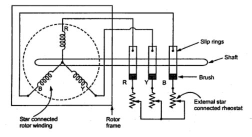
Why the rotor winding of three phase wound rotor induction motor is

What is Step Motor Stack Length? | Applied Motion

Rotor Stator Pumps explained by Putzparts24 - YouTube
